Simple test target

This device is a simple sensor modulated IR broadcast. Its construction is very easy if a universal PCB is used. It can also be built by loosely bonding components.
The principle of the device lies in the fact that the LED goes out for a short moment when capturing the modulated IR signal.
It is suitable for testing and setting of radiators and sight for Lasertag weapons. You can also test the range, which can be slightly larger. The device indicates an intervention even if the message is incomplete. The effect has both design and assembly, when the receiver is shielded against the sky, the sun increases its sensitivity. It is fired in a direct direction when the receiver has the highest sensitivity.
Parts List
| symbol | part | quantity | comment |
|---|---|---|---|
| TSOP4856 | TSOP4856 | 1x | IR Receiver Module 56kHz |
| Q1 | PN2222A | 1x | Bipolar NPN Tranzistor, TO-92 |
| LED1 | 503VC2E-V1-1AC | 1x | LED 5mm Red; 15°; 5000mcd - 20mA - 2,0 V |
| R1 | Resistors 47Ω | 1x | 125mW, 250mW, ... |
| R2 | Resistors 220Ω | 1x | 125mW, 250mW, ... |
| C1 | Capacitor 47uf | 1x | 6V, 10V, .... |
| S1 | Switch | 1x | Any switch |
| BT1 | Battery case | 1x | 3V; 2x AA, 2xAAA |
| --- | PCB | 1x | Universal PCB Strip Grid 30x30mm |
| --- | Box | 1x | Any box |
Calculation of resistance for LEDs
R = (Vs-Vf)/If
(3-2)/0.025 = 40…. 47 Ω Standard Resistor
In case of using other LEDs it is necessary to calculate the correct value of R1 resistance.
Schema

Possible solved PCB and link to the downloaded Eagle project:

Build a Device
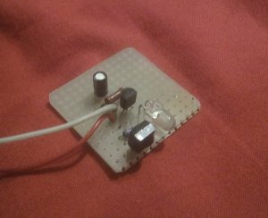
The PCB and the components are přiletují. The ice and TSOP be compared to be parallel.

Device is tested, it is possible to use a regular TV driver
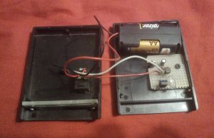
The entire device is eventually placed in a suitable box.


